Showing posts with label Arduino. Show all posts

Sunday, August 23, 2015

Hacking a wireless weather display

A couple of years ago my wireless weather station broke down. Apparently the transmitter of the base unit stopped working and both the indoors display unit and the base station ended somewhere in the attic.
I got a new Alecto DKW-2012 weather station as a birthday present and all was well again (at least for a while...)
One feature both weather stations lacked is logging of data over longer periods. And so a new project was born, using a Raspberry Pi to gather weather related sensor data and store it in a database on my home server. The broken weather station was hacked in all possible ways (new pressure, humidity and temperature sensor) and was mounted next to my other station.


Left: the hacked weather station
Right: Alecto DKW-2012
This setup has been runnning fine for over two years now. The database contains over 1 million samples which I can view using a web browser and the indoor unit displays both time and weather data from the DKW-2012.
Apart from looking a bit silly having two weather stations mounted next to eachother, the indoor unit also suffers from reception problems every now and then.
Wouldn't it be nice to have a single weather station that logs all of its data and at the same time display this data on the wireless indoor display?
I searched the net for any info on the Alecto DKW-2012. The line of Alecto weather stations is very similar (or identical) to units produced by Fine Offset Electronics. They operate at 868.3MHz and are reported to use either FSK or OOK modulation.
Using a DVB-T USB stick I was able to capture the data sent by the base station.


Complete weather data message
Start of message
What I learned from capturing this data (and some research on the net):
  • All data is sent using OOK modulation
  • Bitrate is 2kbit/s (the short yellow  stripes show the bit time of 500us)
  • On air, a binary '1' is encoded as 100 and a binary '0' as 11100
  • The preamble is 0xFF
  • A complete message consists of 11 bytes (including preamble)
  • Messages duration varies, depending on its content, roughly between 130 and 220 ms.

Some code found on the web details the protocol (e.g. nodo) but I couldn't find any project that transmits weather data. I did however find some code by SevenWatt that uses an Arduino and RFM69W to transmit OOK modulated signals.
Using this code as a base, a Moteino with RFM69W and the DVB-T USB stick to analyze the actual on-air data I was able to take control of my wireless indoor display!

'Possessed' DKW-2012 weather display
As a proof-of-concept all values on the display are continuously increased by 3. The Arduino sketch can be found here (for RFM69W connections refer to the Moteino pinouts)

Next step was to actually get some real values from my hacked weather station on the display. My home server, which stores the weather data in a database, also publishes this data to an MQTT broker. A Node-RED installation subscribes to this data and re-publishes each value to topics recognized by an MQTT MySensors Gateway which I wrote some time ago. The gateway distributes these values to wireless sensor nodes in a MySensors network.

I hooked up an nRF24L01+ to the Moteino to be able to communicate with the MySensors network, using the following connections:

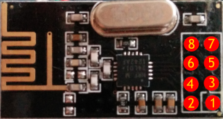
nRF24L01+ module pinout

FunctionMoteino pinnRF24L01+
pin
GND
GND
-
1
3.3V
3.3V
-
2
CE
7
-
3
CSN/CS
8
-
4
SCK
13
-
5
MOSI
11
-
6
MISO
12
-
7
IRQ
--
-
--


This Arduino sketch has the MySensors stack integrated and executes the following tasks:

  • Configure both the RFM69W and the MySensors library
  • Run 3 simultaneous statemachines:
    • Request wallclock time from the MySensors Gateway and send this data as a DCF77 encoded message to the wireless display. This process repeats every hour.
    • Request the weather data we're interested in (temperature, humidity, windspeed, gust, rain) from the Gateway. This triggers automatic subscription to the corresponding MQTT topics. Once the statemachine has received a value for each topic (and thus subscription to all topics has succeeded) it becomes dormant, waiting for new values to be published by the Gateway. When one or more values come in, it triggers the next statemachine:
    • Send sensor data to the wireless display. If no new sensor data comes in for 1 minute, old data is repeated (to prevent the display from blanking after 6.5min without receiving new data)

The same hack also works for an Alecto WS-2900 display!
The hack is running rock-solid, and as a result there is a vacant position on my roof now!

Sunday, July 20, 2014

Changing Arduino bootloader to Optiboot

All Arduino boards come with a pre-programmed boot loader. This boot loader allows you to program the Arduino from the IDE using a serial connection only. After programming the serial connection can be used as a console interface to 'talk' to the Arduino. Other ways exist to program an Arduino, but all of them require extra hardware.

First a big fat warning: Be sure you are familiar with compiling source code from the command line and programming your Arduino using ISP. Failure to update the boot loader might brick your Arduino for usage by the Arduino IDE !!!


Advantages of the Optiboot boot loader

  • Size is only 512 bytes. This leaves more room (flash) for own programs.
  • Works with watchdog enabled.
  • Serial connection speed can be increased (default 57k6). This shortens programming times!

What you'll need

  • An Arduino Pro Mini 3v3 @ 8MHz. This description is for an Arduino Pro Mini (3V3, 8Mhz), but the principle is the same for other ATmega328 based Arduino's)
  • An ISP programmer connected to the ATMega (I use Atmel's JTAGICE3) & software to flash (for JTAGICE3 I use Atmel Studio 6.1)
  • Arduino IDE (I used 1.5.6r2)
The description here assumes Windows.


Compiling Optiboot

  • Download Optiboot 5.0a sources: https://code.google.com/p/optiboot/downloads/detail?name=optiboot-v5.0a.zip
  • Extract to c:\Arduino_1.5.6-r2\hardware\arduino\avr\    (rename existing optiboot directory, when required)
  • Optional: Edit bootloaders\optiboot\Makefile to change the baud rate (line 562) (This is a makefile, so be sure to use tabs to indent instead of spaces!) I went from 57k6 to 76k8, because I got errors at 115k2:
atmega328_pro8: $(MAKE) $(CHIP) AVR_FREQ=8000000L LED_START_FLASHES=3 BAUD_RATE=76800
  • Start a cmd shell in c:\Arduino_1.5.6-r2\hardware\arduino\avr\bootloaders\optiboot
  • make clean
  • make atmega328_pro8


Flashing Optiboot to the Arduino

  • Optional: Use your ISP tool to create a backup of the existing bootloader and fuses.
  • Flash optiboot_atmega328_pro_8MHz.hex using your favourite ISP
  • Set fuses to: Low = 0xFF, High = 0xDE, Extended = 0xFE
  • Close any active Arduino windows


Add support for the new bootloader to Arduino IDE

  • Edit c:\Arduino_1.5.6-r2\hardware\arduino\avr\boards.txt
  • Add (based on Arduino Pro or Pro Mini (3.3V, 8 MHz) w/ ATmega328):
## Arduino Pro or Pro Mini (3.3V, 8 MHz) w/ ATmega328 - Optiboot 76k8
## --------------------------------------------------
pro.menu.cpu.8MHzatmega328ob=ATmega328 (3.3V, 8 MHz, Optiboot 76k8)
pro.menu.cpu.8MHzatmega328ob.upload.maximum_size=32256
pro.menu.cpu.8MHzatmega328ob.upload.maximum_data_size=2048
pro.menu.cpu.8MHzatmega328ob.upload.speed=76800
pro.menu.cpu.8MHzatmega328ob.bootloader.low_fuses=0xFF
pro.menu.cpu.8MHzatmega328ob.bootloader.high_fuses=0xDE
pro.menu.cpu.8MHzatmega328ob.bootloader.extended_fuses=0xFE
pro.menu.cpu.8MHzatmega328ob.bootloader.file=atmega/ATmegaBOOT_168_atmega328_pro_8MHz.hex
pro.menu.cpu.8MHzatmega328ob.build.mcu=atmega328p
pro.menu.cpu.8MHzatmega328ob.build.f_cpu=8000000L


Testing it!

  • Start Arduino IDE
  • Select Board -> Arduino Pro or Pro Mini
  • Select Processor -> ATmega328 (3.3V, 8 MHz, Optiboot 76k8)
  • File -> Upload