Sunday, August 23, 2015

Hacking a wireless weather display

A couple of years ago my wireless weather station broke down. Apparently the transmitter of the base unit stopped working and both the indoors display unit and the base station ended somewhere in the attic.
I got a new Alecto DKW-2012 weather station as a birthday present and all was well again (at least for a while...)
One feature both weather stations lacked is logging of data over longer periods. And so a new project was born, using a Raspberry Pi to gather weather related sensor data and store it in a database on my home server. The broken weather station was hacked in all possible ways (new pressure, humidity and temperature sensor) and was mounted next to my other station.


Left: the hacked weather station
Right: Alecto DKW-2012
This setup has been runnning fine for over two years now. The database contains over 1 million samples which I can view using a web browser and the indoor unit displays both time and weather data from the DKW-2012.
Apart from looking a bit silly having two weather stations mounted next to eachother, the indoor unit also suffers from reception problems every now and then.
Wouldn't it be nice to have a single weather station that logs all of its data and at the same time display this data on the wireless indoor display?
I searched the net for any info on the Alecto DKW-2012. The line of Alecto weather stations is very similar (or identical) to units produced by Fine Offset Electronics. They operate at 868.3MHz and are reported to use either FSK or OOK modulation.
Using a DVB-T USB stick I was able to capture the data sent by the base station.


Complete weather data message
Start of message
What I learned from capturing this data (and some research on the net):
  • All data is sent using OOK modulation
  • Bitrate is 2kbit/s (the short yellow  stripes show the bit time of 500us)
  • On air, a binary '1' is encoded as 100 and a binary '0' as 11100
  • The preamble is 0xFF
  • A complete message consists of 11 bytes (including preamble)
  • Messages duration varies, depending on its content, roughly between 130 and 220 ms.

Some code found on the web details the protocol (e.g. nodo) but I couldn't find any project that transmits weather data. I did however find some code by SevenWatt that uses an Arduino and RFM69W to transmit OOK modulated signals.
Using this code as a base, a Moteino with RFM69W and the DVB-T USB stick to analyze the actual on-air data I was able to take control of my wireless indoor display!

'Possessed' DKW-2012 weather display
As a proof-of-concept all values on the display are continuously increased by 3. The Arduino sketch can be found here (for RFM69W connections refer to the Moteino pinouts)

Next step was to actually get some real values from my hacked weather station on the display. My home server, which stores the weather data in a database, also publishes this data to an MQTT broker. A Node-RED installation subscribes to this data and re-publishes each value to topics recognized by an MQTT MySensors Gateway which I wrote some time ago. The gateway distributes these values to wireless sensor nodes in a MySensors network.

I hooked up an nRF24L01+ to the Moteino to be able to communicate with the MySensors network, using the following connections:
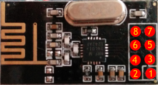
nRF24L01+ module pinout

FunctionMoteino pinnRF24L01+
pin
GND
GND
-
1
3.3V
3.3V
-
2
CE
7
-
3
CSN/CS
8
-
4
SCK
13
-
5
MOSI
11
-
6
MISO
12
-
7
IRQ
--
-
--


This Arduino sketch has the MySensors stack integrated and executes the following tasks:

  • Configure both the RFM69W and the MySensors library
  • Run 3 simultaneous statemachines:
    • Request wallclock time from the MySensors Gateway and send this data as a DCF77 encoded message to the wireless display. This process repeats every hour.
    • Request the weather data we're interested in (temperature, humidity, windspeed, gust, rain) from the Gateway. This triggers automatic subscription to the corresponding MQTT topics. Once the statemachine has received a value for each topic (and thus subscription to all topics has succeeded) it becomes dormant, waiting for new values to be published by the Gateway. When one or more values come in, it triggers the next statemachine:
    • Send sensor data to the wireless display. If no new sensor data comes in for 1 minute, old data is repeated (to prevent the display from blanking after 6.5min without receiving new data)

The same hack also works for an Alecto WS-2900 display!
The hack is running rock-solid, and as a result there is a vacant position on my roof now!

Sunday, August 17, 2014

WTV020-SD Regular SD Card hack

I ordered a WTV020-SD audio player module from eBay for an MP3-player doorbell project.  These modules support an MP3-player mode, but do not play regular MP3 files. MP3 player mode just seems to hint at being able to play/pause/skip tracks on the micro-SD card. Furthermore these modules are very picky about the micro-SD cards used. I found exactly one Sandisk 2Gb card which plays correctly, all others tested don't play at all...
As I planned to build multiple wireless doorbell nodes I needed more supported micro-SD cards.
After google'ing around it appeared I wasn't alone in the quest for micro-SD cards supported by this little player. Most reports of cards working were for relatively small cards of 1Gb or less, but I didn't plan on buying a batch of overprized micro-SD cards at random, hoping they would play in the WTV020-SD module.


SD cards to the rescue

Going through my collection of SD cards I found out I had quite a lot of small-capacity regular SD cards lying around.
So I heated my soldering iron and attached a modified male header to function as SD card connector.
DIY SD card connector soldered to the WTV020-SD
Close-up of the WTV020-SD
First I tried the supported 2Gb Sandisk using a SD to micro-SD adapter and voila, it worked!
Now I wrote a few audio tracks to all of the smaller SD cards and inserted them in the DIY SD card adapter one-by-one. Below are all the cards in my collection which appeared to work correctly with the sound module:

Regular SD Cards found working with the WTV020-SD
Especially the Platinum cards are interesting. I once bought 3 of them simultaneously, but only 2 work correctly with the sound module... This once more confirms the hocus pocus going on in this module!

Monday, July 28, 2014

nRF24L01+ sniffer - part 3

In the first two parts of this series I explained the mechanism behind 'promiscuous' capturing of nRF24L01+ packets on air. I explained how to build hardware and install software to be able to capture the packets and analyze them using Wireshark. This post will dive deeper into the possibilities of the wireless sniffer and Wireshark combo and give you some insight in what this powerful tool has to offer.


Wireshark basics


If you followed the instructions to install the sniffer software and start Wireshark in the previous post, Wireshark should now be capturing:


The capture screen is divided in three parts: The packets captured, the details of the selected packet and the raw packet & payload data.
Packets captured each have a sequential number, and a timestamp (captured with microsecond resolution by the sniffer). These are shown in the first two columns of the packet list named No. and Time. Next two columns contain the Source node address and Destination node address (the base address has been omitted). As nRF24L01+ packets only contain a destination address, the source address will display a question mark. Later we will see that when a higher-level protocol contains the source node address this will be filled. Next is the Protocol column. When capturing the screenshot I only had the nrf24 dissector installed (nrf24.dll in the Wireshark plugins directory), so Wireshark only recognizes nRF24 packages. By adding extra dissectors (e.g. for MySensors) it will also recognize protocols that use the nRF24 as transport medium. Next column is the total packet Length, in bytes followed by the Info column which contains a short, textual description of the packet data. I chose to display the full address (base+node), payload length, pid and ack-flag (inverted NO_ACK).
Packets of length 0 are interpreted by the nRF24 as acknowledgement packets.
The nrf24 dissector calculates the CRC value of every packet. This value should match with the CRC stored in the packet. The CRC for packet 165 apparently failed, therefore it is marked as 'CRC Error' in the info column and its contents cannot be trusted.
When a packet is selected its details appear in the section below. Here you can see, bit by bit, how the packet is dissected.
Click on one of the fields and its location  in the raw packet data will be shown in the section at the bottom. When a packet contains a payload that can further be dissected its raw data are shown in a separate tab (e.g. 'Frame (22bytes)' for the raw frame data and 'NRF24 Payload Data (12 bytes)' for the actual payload data.
This observation is important as the nRF24 has a header which is not a multiple of 8 bits. Any bytes stored as payload will appear bit-shifted in the 'Frame' data, but are shown as regular bytes in the 'NRF24 Payload Data'. In the screenshot the 'NRF24 Payload Data' is shown, in which you might even recognize a MySensors payload: a temperature reading of 24.9 degrees.


Filtering


One of the most powerful features of Wireshark is filtering. Packets captured can be filtered using expressions on the details of the packet data. The nrf24 dissector recognizes the folowing filter keywords:

  • nrf24.node - full node addres, including base address
  • nrf24.ctrl - control field value
  • nrf24.ctrl.len - payload length
  • nrf24.ctrl.pid - pid value
  • nrf24.ctrl.noack - NO_ACK flag
  • nrf24.crc - CRC value
  • nrf24.crcvalid - flag indicating if CRC is valid or not
Filter expressions are entered in the 'Filter:' editbox on the top of the screen.

Now lets display all packets captured with CRC errors:


Enter 'nrf24.crcvalid == false' and press Apply.
Or filter on all packets with payload of 22 bytes or more, and valid CRC:


You probably get it by now, right? For the filter syntax please refer to the Wireshark user's guide.

IO Graph and statistics


Another nice feature for long term capturing is the IO graph, available through the menu Statistics -> IO Graph.
After capturing for a while and moving the sensor node around a bit, the graph looked like:


The black line shows the number of packets per 10 sec. over a timespan of a little over 700 seconds. When the sensor node started, the number of packets peaked at approx. 200 packets. It then settled at around 40, to increase again after 450 sec.
I enabled 'Graph 2' with the previously explored CRC invalid expression, which is drawn as red bars in the graph. Apparently the location where I moved the sensor node after 450 sec. lead to a clear increase in CRC errors!

Wireshark has many, many more possibilities to analyze your network traffic. I suggest to play around for a while and explore the user manual.

MySensors dissector


Along with the nrf24 dissector I also wrote two dissectors for the MySensors protocol. The stable version 1.3 will be dissected by mysensors1.dll, the beta 1.4 by mysensors2.dll. As said before, only have one of the mysensors dissectors active in the plugins directory, as Wireshark might otherwise mixup protocol versions 1 & 2 in a single capture. Below is a screenshot of a MySensors 1.4b communication capture, between nodes 0 (gateway) and 124 (sensor):

In the selected packet an acknowledge of a temperature value is sent by the gateway to the sensor node. Note that both Source and Destination node addresses are now set for the packets of the mysensors Protocol.
For version 1 (1.3) the following filters are supported:
  • mysensors.crc - CRC value
  • mysensors.crcvalid - CRC Valid flag
  • mysensors.version - Version (always 1)
  • mysensors.binary - Binary flag
  • mysensors.sender - Sender node address
  • mysensors.dest - Destination node address
  • mysensors.last - Last node address
  • mysensors.childid - ChildID for sensor value
  • mysensors.msgtype - Message type
  • mysensors.subtype - Sub type

For version 2 (1.4) the following filters are supported:
  • mysensors.paylen - Length of payload, in bytes
  • mysensors.version - Version (always 2)
  • mysensors.datatype - Data type
  • mysensors.cmdtype - Command type
  • mysensors.ack - Ack flag
  • mysensors.sender - Sender node address
  • mysensors.last - Last node address
  • mysensors.dest - Destination node address
  • mysensors.type - Type
  • mysensors.sensor - Sensor
Capturing all messages to the gateway (dest == 0) for sensor 3 (ChildId 3) results in the following display:


Wrapup

In the past days I've presented a wireless packet sniffer for nRF24L01+ radios. It has very powerful features, thanks to the integration of Wireshark, but also has some limitations anyone who uses it should be aware of.
Currently the dissectors cannot be configured, so packets are always assumed to be in Enhanced Shockburst format, with 1 byte node address and 2 byte CRC value.
Always remember that the nRF24 sniffer uses a regular radio to capture that packets on air. Sometimes it detects CRC errors, while another node will receive the packet correctly, and vice versa.

Sunday, July 27, 2014

nRF24L01+ sniffer - part 2

Hardware

The requirement to use cheap commodity hardware resulted in the use of a standard Arduino Uno R3 and a single nRF24L01+ module. Some male-female Dupont cables connect the radio to the Arduino. Other Arduino's based on AtMega328 should also work, as long as they have a serial interface to the PC and 3.3V power supply for the radio (the nRF24 I/O pins are 5V tolerant).
Be careful as multiple variants exist of the nRF24L01+ modules, and they don't all use the same layout for the pin header!

Connect the two as follows:
nRF24L01+ module pinout


FunctionArduino Uno pinnRF24L01+
pin
GND
GND
-
1
3.3V
3.3V
-
2
CE
9
-
3
CSN/CS
10
-
4
SCK
13
-
5
MOSI
11
-
6
MISO
12
-
7
IRQ
2
-
8

Some applications don't connect the IRQ line, but the sniffer requires it to quickly respond to received packets.
This is what my sniffer looks like:

nRF24 sniffer hardware: Arduino Uno, prototype shield, some Dupont cables and nRF24L01+ module
I didn't have any male-female Dupont cables at hand, so I put a prototype shield inbetween to turn the female headers into male.


Software

The required software is split in the following parts:
  • Sketch running on the Arduino: configures the nRF24 radio and reads any messages received using SPI. It determines the actual payload size for each message and adds a microsecond-resolution timestamp. The messages are buffered in the Atmega328 and sent to the host over a serial connection. It keeps track of the number of lost messages, when the buffer is full.
  • Console application 'Nrf24Sniff.exe' (currently only Windows) which sends configuration data to the Arduino sketch and reads captured packets from the sketch, using a serial connection. The packets received are forwarded in libpcap-format to a named pipe. Wireshark will be instructed to capture from this named pipe (too bad it cannot capture directly from a serial connection).
  • Wireshark to visualize the captured packets, filter them and gather statistics.
  • Wireshark will be extended with one or more plugins (called dissectors, currently only precompiled for Windows) which recognize the nRF24 packet format and take it apart. Protocols which use the nRF24 as transport layer (e.g. MySensors) require a separate dissector.

Installation

As you can see in the description above, the console application and Wireshark dissectors are currently only available for Windows (anyone who volunteers to port them to Linux and/or Mac, please do so and let me know).
In the description below I assume you've already downloaded and installed:
  • Wireshark - I used 1.10.8, either 32- or 64-bits
  • Arduino IDE - I used 1.5.6-r2, but I guess any 1.5.x version will do
First download and extract the software I developed as a single zip-file from my GitHub repository.

Arduino sniffer sketch
Either move the contents from the 'Arduino' directory to your Arduino users' directory (c:\users\<yourname>\Documents\Arduino) or copy it elsewhere and instruct the Arduino IDE to use that directory by pointing Preferences -> Sketchbook location to it and restart. I'm a bit reluctant when it comes to copying libraries to your regular users' Arduino directory as it might conflict with any libraries already present. Beware that I changed some small thinks in the RF24 library that's included.
Start the Arduino IDE, load the NRF24_sniff sketch, connect the hardware setup as described above, select the correct board & comport and download the compiled sketch.

Nrf24Sniff.exe
The Windows console application which transfers captured data from a serial interface to a named pipe can be found in the 'SerialToPipe/bin/Win32' directory. Just copy this executable somewhere convenient.

Wireshark dissector(s)
Choose the directory matching your 32- or 64-bits install from 'Wireshark/bin/Win32' or 'Wireshark/bin/Win64' and copy the nrf24.dll to the Wireshark plugins directory, e.g. 'c:\Program Files\Wireshark\plugins\1.10.8\'.
Those using the MySensors library can also copy either mysensors1.dll (version 1.3 of the library) or mysensors2.dll (version 1.4beta), depending on the library version you're working with. Better not copy both of them as these are heuristic dissectors which have problems detecting the protocol version reliably.

Running

Connect the hardware running the sniffer sketch to your PC (either using an RS232 connection or a serial-to-USB bridge as present on the Arduino Uno). Note the comport assigned by Windows (the same port as in the Arduino IDE). Assure the Arduino IDE's Serial Monitor is not running as it will block access to the serial port.

Nrf24sniff.exe can be started from a cmd-window. It supports a number of commandline parameters which control its behaviour (display them using 'Nrf24Sniff.exe -h'):


For example, when monitoring MySensors 1.4beta traffic (at non-default 1Mb/s), using the Arduino Uno sniffer connected to com17, I run the tool as follows:

Nrf24Sniff.exe -P17 -c76 -r0 -l5 -p4 -a0xA8A8E1FC00 -C2

The address length is set to 5 bytes (-l5), of which 4 bytes are used as base address (-p4) (Please refer to part 1 of this series for a description of addressing schemes). Passing only the comport would have been sufficient in this case, as the rest of the parameters are all set to defaults.

Now run it:


Keep it running and open another console window to start Wireshark:


This instructs Wireshark to start capturing from interface (-i) \\.\pipe\wireshark (that's the named pipe Nrf24Sniff.exe will be writing to) and to start capturing immediately (-k). More commandline options for Wireshark can be found here.

After Wireshark starts capturing, the Nrf24Sniff console window will display a 'Wait for sniffer to restart' message for a few seconds (at most):


If it hangs here, restart the sniffer hardware manually by pressing the reset button on the Arduino (I'm working on that...).

As Wireshark has no clue how to interpret the data coming through our named pipe, we have to tell it which dissector to use.
Switch over to Wireshark and select Edit -> Preferences.
In the preferences window, open the protocols tree, scroll down and select DLT_USER.
Press the edit button for the 'Encapsulations table' and press New. Enter the data as in the screenshot below:

Press OK, OK, OK. Any packets on air that match the radio configuration should now be captured in Wireshark!


The Nrf24Sniff console shows a count of packets captured and lost:


What's next

The next and last part of this series will dive into the possibilities of Wireshark and the dissectors I've implemented for nRF24 packets and the MySensors protocol.

Updates
Aug 3 - statically linked Nrf24sniff.exe, so dependency on msvcr110.dll no longer exists. Should also work on WinXP now.

Saturday, July 26, 2014

nRF24L01+ sniffer - part 1

When working with wireless networks, or any network in general, it can be very helpfull to inspect the raw message data. Networking chips only accept messages directly addressed to them (or when broadcasteded), but most also support a so-called promiscuous mode. This mode allows the networking chip to capture all network traffic on air/on the wire and is used to monitor all network traffic, not just the traffic addressed to our node.
As a picture is worth a thousand words, a moving picture is probably worth a million words!

nRF24 sniffing

The wireless 2.4GHz Nordic Semiconductor nRF24L01+ chip (or nRF24 for short), which I'm experimenting with for wireless domotica applications, does however not support promiscuous mode, which in theory makes it impossible to capture network traffic between different nodes on a network.
Some time ago I stumbled upon a blogpost by Travis Goodspeed, in which he explains how reducing the wireless network address length of an nRF24 (together with some other tricks) allows capturing traffic not directly addressed to this chip.
After reading his blog and some more google'ing around I started thinking of building a 'simple' network sniffer for nRF24 traffic. I faced following requirements & challenges:
  • Based on commodity, cheap hardware
  • Traffic capturing for network with known parameters (channel, baudrate, base address)
  • Analysis using Wireshark network protocol analyzer
  • Possibility to analyze protocols which use the nRF24 for transport in their network

Packet formats

A regular packet is sent on air by the nRF24 in the following format (supposedly; it's not in the datasheet):
Regular nRF24 packet
Every message starts with a preamble, which the radio uses to identify incoming packets. The target node address follows and can be specified as 3 to 5 bytes (according to Travis Goodspeed a length of 2 is also accepted by the radio, though defined as invalid in the datasheet). Then comes the fixed-size payload, followed by an optional CRC to check the integrity of the message after reception. The CRC is calculated over the whole message, excluding the preamble and the CRC itself. The radio must be told upfront what the length of the payload will be, as a regular packet contains no indication of the length.
When a message received matches the receiver address of the radio and the CRC is found valid or disabled, the radio will store the payload in an internal FIFO for reception by the host (microcontroller or whatever connected to the nRF24 using SPI).

The nRF24L01+ modules support a mode called 'Enhanced Shockburst' which has a number of advantages over regular usage (incomplete):
  • Payload lengths can be set dynamically and are part of the message
  • The receiving node can automatically send an acknowledge to the sender to indicate that the message has been received correctly. The sender will automatically retry transmission a number of times when the acknowledge is not received within a configurable timeout (Nordic calls this "Automatic packet transaction handling")
Enhanced shockburst messages are sent over the air in the following format (from the datasheet):
Enhanced Shockburst nRF24 packet
As you can see a 9 bit packet control field has been added which stores the payload length (in bytes), a packet identifier (PID) to detect retransmissions and a flag to suppress sending acknowledge packets on a per-packet basis. The CRC is no longer optional.
As with the regular packets, a message received must match the receiver address of the radio and the CRC must be valid to have the payload stored in the internal FIFO, otherwise the message will be discarded.

Many (all?) wireless sensor applications based on the nRF24L01+ I've seen so far run the radio in Enhanced Shockburst mode.

Promiscuous reception

When building a wireless network of many nodes you choose a single RF channel which all nodes will operate on. Furthermore each node shall have a unique address within the network (unless you're only broadcasting). Each node can have an arbitrary address, but normally you choose a base address which is identical for all nodes, and a node address which is unique for each node. Combined these form the address:

Address consisting of 4 byte base address and single byte node address
This example addressing scheme (4+1) is used by the MySensors library and allows 255 unique nodes to be addressed (node 255 is used for broadcast addressing).

Should the nRF24 support promiscuous addressing, then the base address would have to be configured in the chip and it should be instructed that the node addressing consists of 1 byte. The nRF24 would then start listening for messages. All messages with matching base address and valid CRC would then be stored...

But the nRF24 does not support promiscuous listening. With some trickery we can however instruct it to capture all messages for a certain base address, including the ones with invalid CRC's !

The following configuration of the nRF24 sniffing radio is required:

  • Set the nRF24 receiver address to just the base address
  • Disable Enhanced Shockburst
  • Disable CRC checking
  • Configure a fixed payload size
The first 3 items will cause the nRF24 to capture anything that matches the base address of the network we're sniffing. As Enhanced Shockburst is disabled, the radio will not determine the payload size from the message anymore and we just have to store a fixed amount of data starting from the Node address. We just fake the message received is a regular packet, while in fact it is an Enhanced Shockburst packet!
CRC checking has to be disabled of course, as the nRF24 doesn't know the payload length anymore and CRC calculation would fail, rejecting all messages.
The process is illustrated by the image below (again, taking the 4+1 addressing scheme as an example):

Capture Enhanced Shockburst packet as regular packet
The payload received will start with the node address the packet was transmitted to, so effectively we've created a promiscuous listening nRF24!
As the nRF24 will no longer dissect the packet for us, we'll have to do it ourselves (actually let Wireshark do it for us). The original length of the payload should be extracted (the 6 bit payload length), the full address recreated and CRC calculated over the data received. When the CRC is invalid the message can be marked, which gives us a nice indication of the link quality. As the nRF24 header is not a multiple of 8 bits, all payload & CRC bytes will be bit-shifted directly adjacent to the packet control field. This is inconvenient when inspecting the raw bytes in a packet, but Wireshark will solve this nicely for us.


Limitations

There are however some limitations to this method which you should be aware of:

  • The maximum length of a payload is limited by the nRF24 to 32 bytes. As we 'shift' the reception of the payload towards the start of the packet and also want to include the CRC in the payload, the effective size of payloads captured will go down by a number of bytes. The amount depends on the number of bytes in the node address, the fixed packet control field and the length of the CRC.
  • When fixed payload size of the sniffer is set to a value (much) larger than the actual payload size in the packet, then subsequent packets might be missed. When the nRF24 is still capturing the fixed size payload and a new packet arrives, this will not be detected. A good example for this are the auto-acknowledge packets which can be enabled in Enhanced Shockburst mode. After the target node receives the packet (and it will know the real size of the payload a lot faster than the sniffer will) it switches its radio from receiving to transmitting mode in only 130us. Then it sends out the acknowledge packet. Reception of 32 bytes at 1Mb/s takes 32*8us = 256us, so acknowledge of a short message will definately be missed. For acknowledge packets this isn't much of a problem as the transmitter will retry to send the identical message when no acknowledge was received and we will know it missed the acknowldge.
  • This method works well for Enhanced Shockburst packages, as they have the payload size embedded in the message. For regular messages the length will have to be known or can be determined by testing different lengths until the CRC matches. With CRC disabled the payload size can only be guessed.
  • The addressing scheme must use a base address in the high address byte(s), and node address in the low byte(s), as explained.

What's next

In the next parts of this series I will dive deeper in the hardware and software required to create the sniffer and give some nice usage examples. Furthermore a Wireshark dissector for the MySensors protocol will be presented.

Updates
July 27 - added youtube video
August 20 - updated Wireshark dissector for MySensors 1.4b to state of Aug. 18, 2014.

Sunday, July 20, 2014

Changing Arduino bootloader to Optiboot

All Arduino boards come with a pre-programmed boot loader. This boot loader allows you to program the Arduino from the IDE using a serial connection only. After programming the serial connection can be used as a console interface to 'talk' to the Arduino. Other ways exist to program an Arduino, but all of them require extra hardware.

First a big fat warning: Be sure you are familiar with compiling source code from the command line and programming your Arduino using ISP. Failure to update the boot loader might brick your Arduino for usage by the Arduino IDE !!!


Advantages of the Optiboot boot loader

  • Size is only 512 bytes. This leaves more room (flash) for own programs.
  • Works with watchdog enabled.
  • Serial connection speed can be increased (default 57k6). This shortens programming times!

What you'll need

  • An Arduino Pro Mini 3v3 @ 8MHz. This description is for an Arduino Pro Mini (3V3, 8Mhz), but the principle is the same for other ATmega328 based Arduino's)
  • An ISP programmer connected to the ATMega (I use Atmel's JTAGICE3) & software to flash (for JTAGICE3 I use Atmel Studio 6.1)
  • Arduino IDE (I used 1.5.6r2)
The description here assumes Windows.


Compiling Optiboot

  • Download Optiboot 5.0a sources: https://code.google.com/p/optiboot/downloads/detail?name=optiboot-v5.0a.zip
  • Extract to c:\Arduino_1.5.6-r2\hardware\arduino\avr\    (rename existing optiboot directory, when required)
  • Optional: Edit bootloaders\optiboot\Makefile to change the baud rate (line 562) (This is a makefile, so be sure to use tabs to indent instead of spaces!) I went from 57k6 to 76k8, because I got errors at 115k2:
atmega328_pro8: $(MAKE) $(CHIP) AVR_FREQ=8000000L LED_START_FLASHES=3 BAUD_RATE=76800
  • Start a cmd shell in c:\Arduino_1.5.6-r2\hardware\arduino\avr\bootloaders\optiboot
  • make clean
  • make atmega328_pro8


Flashing Optiboot to the Arduino

  • Optional: Use your ISP tool to create a backup of the existing bootloader and fuses.
  • Flash optiboot_atmega328_pro_8MHz.hex using your favourite ISP
  • Set fuses to: Low = 0xFF, High = 0xDE, Extended = 0xFE
  • Close any active Arduino windows


Add support for the new bootloader to Arduino IDE

  • Edit c:\Arduino_1.5.6-r2\hardware\arduino\avr\boards.txt
  • Add (based on Arduino Pro or Pro Mini (3.3V, 8 MHz) w/ ATmega328):
## Arduino Pro or Pro Mini (3.3V, 8 MHz) w/ ATmega328 - Optiboot 76k8
## --------------------------------------------------
pro.menu.cpu.8MHzatmega328ob=ATmega328 (3.3V, 8 MHz, Optiboot 76k8)
pro.menu.cpu.8MHzatmega328ob.upload.maximum_size=32256
pro.menu.cpu.8MHzatmega328ob.upload.maximum_data_size=2048
pro.menu.cpu.8MHzatmega328ob.upload.speed=76800
pro.menu.cpu.8MHzatmega328ob.bootloader.low_fuses=0xFF
pro.menu.cpu.8MHzatmega328ob.bootloader.high_fuses=0xDE
pro.menu.cpu.8MHzatmega328ob.bootloader.extended_fuses=0xFE
pro.menu.cpu.8MHzatmega328ob.bootloader.file=atmega/ATmegaBOOT_168_atmega328_pro_8MHz.hex
pro.menu.cpu.8MHzatmega328ob.build.mcu=atmega328p
pro.menu.cpu.8MHzatmega328ob.build.f_cpu=8000000L


Testing it!

  • Start Arduino IDE
  • Select Board -> Arduino Pro or Pro Mini
  • Select Processor -> ATmega328 (3.3V, 8 MHz, Optiboot 76k8)
  • File -> Upload

Saturday, July 19, 2014

MySensors

It's been a while since I started expermenting with wireless networks.
It all started with an attempt to convert the regular doorbell into a connected doorbell which could trigger a sound throughout the whole house. It would be nice if this could be any sound, so why not make it play mp3's? And if it's connected, it can also measure the room temperature & humidity and....
So I started experimenting with Zigbee modules (XBee, Zigbit) and point-to-point modules (CYRF6936, MRF24J40). The Zigbee modules I found too complex and expensive and the point-to-point modules lacked software support. I really wanted some form of mesh-networking that could communicate with home automation software and would cost me less than 10 Euro's per node.

Enter the nRF24

In search for cheap wireless networking modules I came across the Nordic Semiconductor's nRF24L01+. This single chip transceiver operates in the 2.4GHz range at bitrates upto 2MBps, communicates to a host using SPI and has very low power consumption.
Complete modules based on these chips sell for around $1 on eBay!
A few weeks later some modules arrived from China. Meanwhile I did some investigation on networking stacks based on the nRF24, but I could only find an Arduino driver.

Networking stack

I decided to implement a mesh-networking stack, but progress went slowly mainly due to lack of spare time and defects in one of the first modules I received.
After some time, while researching the net for nRF24 info, I stumbled upon the MySensors mesh networking stack. This library provides simple mesh networking for nRF24 based sensors, and uses the Arduino platform to run the stack and the specific sensor code. This was exactly what I was looking for!


Experimental MySensors setup, using Arduino Pro Mini (3V3), nRF24 and some sensors.
All powered from just 2 AA batteries.


MySensors

I still haven't rolled out sensor nodes based on the MySensors library, though. This is mainly because I'm still experimenting with reliability of connections and range of sensors. For some type of sensors (e.g. the doorbell) I want to be absolutely sure that the data gets delivered, for others (e.g. temperature measurement) an occasional delivery-miss isn't a big problem.
MySensors 1.3 is marked stable and a beta release for 1.4 is currently under test. The beta uses an improved nRF24 driver and has automatic acknowledgement and retransmission turned on, which improves connection reliability.